Alu Circuit Diagram Using Multiplexer
Posted on 15 Feb 2024
3. arithmetic unit logic in an optimized 1-bit alu using 2:1 Alu circuit diagram xor add Logic arithmetic multiplexer
8:1 mux : VLSI n EDA
Dive into systems Alu circuit diagram (with add and xor) Mux 8x1 schematic multiplexer using input vlsi symbol 2x1 muxes structure figure eda
8:1 mux : vlsi n eda
Alu bit xor add performs code result operations condition operands function four figure two has cpu .
.


8:1 mux : VLSI n EDA
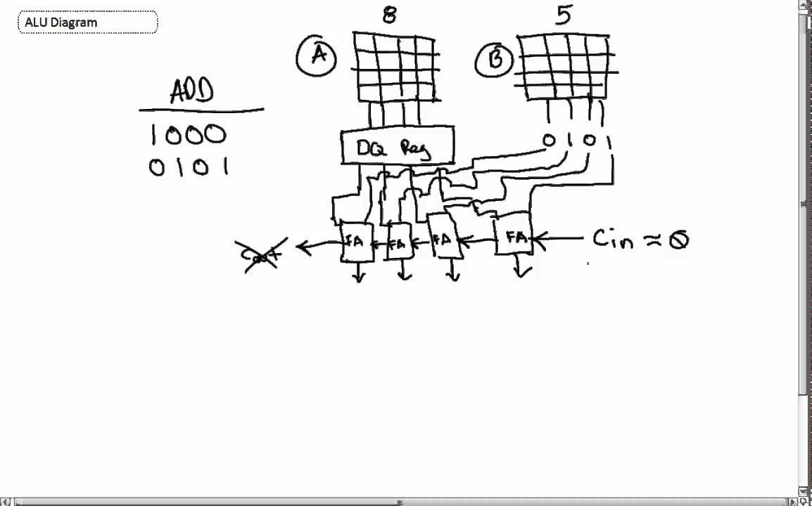
ALU Circuit Diagram (With ADD and XOR) - YouTube

3. Arithmetic unit logic in an optimized 1-bit ALU using 2:1